Norwin 225 kW - Main Features of Design The origin of this turbine goes 17 years back, with the first prototype installed in 1984, and with not less that 365 turbines installed in Denmark, USA, Germany and Sweden. The design philosophy for this turbine has resulted in a both simple and robust turbine. Despite of the small size compared to the main stream size of turbines, it is still a very cost-effective turbine. It is ideally suited for installation by customers who only want to have a small but reliable power installation, or for use together with stand-alone system. This is naturally also the reason why Norwin has kept this turbine in our program, where most other manufacturers have decided not to produce this size of turbine any more. The Norwin 29-STALL-225 kW is a stall regulated wind turbine with a rotor diameter of 29 m and a generator size of 225 kW. For this size of turbine, it was decided to use the most mechanical simple type of power control system, which is stall control. Stall control is a passive way of limiting the power from the turbine in strong winds. What happens is that when the wind rises above a certain speed, the blade starts to stall, and looses some of the lift that drives the rotor, and thus the power output from the turbine. The stall control method lacks several of the advantages of the Active Stall Regulation method (ASR) used in the larger size Norwin turbines. However, for a turbine this size, it is important to keep building and maintenance costs at a minimum. Moreover, it is a fact that the benefits from ASR rise much more with size of turbine than the installation and maintenance costs for the system. This is why we use stall control on this size of Norwin turbines: ‘When simplicity makes sense’! In the following, some of the main features of design for this turbine will be presented. A pleasure to behold inside and out! An aluminum ladder with safety railings leads to the nacelle. The interior is fully lit, and there are rest platforms along the way. Hathes allow for inspction of blade tips, without use of a lift or hoist. The tower is a tube tower and it stands as a sooth, unbroken conical column. The steel sections are bolted together from the inside, and all joints are welded using the submerged arc welding technique for maximum fatigue strength. NORWIN wind turbines put an end to cramped crawling about on exterior ladders and bridges. Up through the tower and straight into the nacelle, whether the wind turbine is operating or not. The nacelle is spacious enough for two to be working at a time. There is interior lighting and standard service checks can be accomplished without ever opening the hatches. Meaning that work can go on, whatever the weather. All by design Rotor: Heart of the matter NORWIN wind turbine’s great effectiveness is partly based on its blades, which are of top quality. The blades are manufactured for NORWIN by LM Glasfiber, one of the world’s largest producers of wind turbine blades. The fiberglass reinforced polyester used to make the blades yields superior strength and a smooth surface. Safety brake Energy from 4 m/s Main frame: simple, solid T-construction For this turbine NORWIN has however build the main frame in a T-construction cast in SG-iron. The main bearings are mounted in integrated surfaces of support at each end of the main tube, i.e. the main shaft is placed inside the tube. Force is transferred to the tower through three strong slide claws, performing an ideal distribution of forces, which allows for both a light and very rigid construction. The main frame is machined to produce exact surfaces of support for bearings, generator, yaw gears and slide claws. The simple construction provides direct access to the nacelle form the closed tower. Yawing system: protection from battering conditions Attached to this are the three strong slide claws securing the main frame! They also maintain its horizontal position. The wear surfaces can easily and inexpensively be replaced, not requiring the main frame to be dismounted. The nacelle is secured by three hydraulic yaw brakes, when not yawing. This ensures that random and rough conditions will not affect the yaw gear. Before yawing begins, the brake is released. Yawing movement is activated by two identical yaw drives. Each consists of an electrical motor. A powerful gear turns a smaller pinion wheel, which, in turn, engages the large cogged ring. Yawing is initiated by a wind vane via the control system. A slight delay has been programmed to prevent sudden, minor shifts in wind direction from triggering yawing. Independent main shaft and bearing supports The main shaft is forged and made of special chrome-nickel-molybdenum steel. It is mounted in the main frame with two strong, double spherical roller bearings. The bearings have low-friction labyrinth seals with no sliding parts and require neither maintenance nor replacement. When lubricating, fresh grease is forced into the bearings’ center. Hence, the new grease forces the old out. Periodic dismantling and cleaning is not necessary. The gearbox The NORWIN gearbox is a powerful, 3-stage hollow shaft gear mounted directly onto the main shaft. This ensures automatic centering. The torque is transferred from the main shaft by means of a shrink disc. Concentrations of tension that typically arise with standard torque and groove connections are avoided – and thus the standard risk of fatigue breaks. NORWIN mounts the shrink disc on the side of the gearbox facing the main shaft. In this position, there is no danger of slippage or wear and tear on the shaft where it enters the gearbox. The gearbox’s torque rod has link bearings at both ends. The gears’ motions are absorbed without slack or internal tensions on the rod. The bearings are tightened with labyrinth seals. Pressure lubrication of the gear reduces the amount of oil in the gearbox. The oil pump is powered by an electric motor. By running the oil pump before start and the rotor can run freely at low rpm and still be well lubricated, even after a stand still period. The induction generator Cooled sufficiently as it is in the NORWIN turbine, The closed type generator is cooled on the outer surface, meaning that the windings are not exposed to humidity and contamination from the cooling air. As a further prevention against humidity during standstill, the generator is equipped with heating elements if necessary. The generator is protected against overload using two separate systems for monitoring the temperature in the windings. A double, flexible clutch has been mounted between the generator shaft and the gearbox’s high-speed shaft. This is in order to protect both the bearings in the gearbox and in the generator against transmission torque peaks, and small misalignments of the gear and generator shafts. Doubly-secured brake system This brake is able to brake down the turbine even in case of a malfunction in the aerodynamic brake (a very unlikely situation). The brake is further a condition for keeping the high standard for personal safety, where it is vital that the turbine in very short time can be brought to a complete standstill. A cast steel brake disc has been placed on the high-speed shaft of the gearbox. The braking takes place with two symmetrically placed calipers of the fail-safe type. This means that they have a reverse action, i.e. hydraulic pressure inhibits – rather than activates the brakes. A break-down in the hydraulic system will thus activate the brake and not lead to a brake failure. Since a full emergency braking eats a certain potion of the gearbox lifetime, it is unwise to use the full emergency breaking torque each time the turbine brakes. For this reason, the brake is equipped with a soft brake device for use in all non-critical braking situations. The function is that the brake torque increases slowly and only to the necessary level. This is normally around 60% of the maximum torque. In case of i.e. grid failure or emergency button stop, the brake will immediately supply full torque. Electronic supervision of operation and production This occurs via our optional remote monitoring system with direct contact to each NORWIN wind turbine. A computer screen is connected with the telephone network. All that might be necessary for surveillance and remote control of the wind turbine can be communicated through a telephone plug. NORWIN’s computerized surveillance is an extra service, contracted on an individual basis, which ensures maximum security, productivity and longevity. Electronic surveillance of four types: It generally conducts four types of:
Electronic control of the turbine’s operation comprises yawing the turbine according to wind direction, start (if necessary) by means of motor when the wind-speed is sufficient, and cut-in and cut-out of the generator. The cut-in and cut-out procedures of the generator are carried out by means of thyristors which ensure a gradual connection to and from the grid. (Soft cut-in). Safety surveillance will monitor possible faults in the turbine or non-favorable conditions and, if necessary, bring the turbine to a standstill. Should the wind turbine come to a standstill due to some unacceptable condition, it will start up automatically when proper conditions have been restored, e.g., after grid failure. When faults require service, e.g. worn brakes, the turbine will, naturally, not be able to start up again until the fault has been corrected. Safety concept If one of the safety-chains is interrupted, an emergency-switch-off takes place by activating both mechanical and air brakes immediately at the same time. The directly wired safety system is activated in case of failure of the electronic system. It activates the rotor brakes by switching-off the hydraulic valve and the emergency system of the control unit. It works in case of grid failure, nacelle vibration, over-speed (10% over rated speed, measured on the main shaft) or pushing an emergency stop button. |
|
|
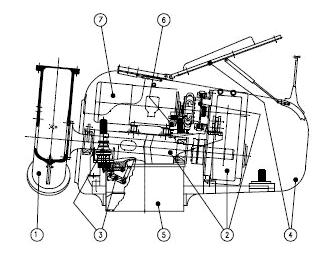
1. Rotor system 2. Mechanical transmission 3. Yaw system 4. Nacelle cover 5. Tower 6. Hydraulic station 7. Generator |

|
|
|
|
|
|